JIANGSU YANGZI RIVER PIPE INDUSTRY CO., LTD.
CONTACT:杨 小 兵
Tel:0523-88809980
Moible:13905267689
Email:yxb@yzjbwg.com yxb@yzjbwg.com
Fax:0523-88800917
Website:www.yzjbwg.com
Add:No. 8, Wanzhong Industrial Park, Tianmushan street, Jiangyan District, Taizhou City
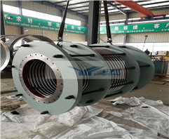
The theoretical basis of metal bellows design is plate and shell theory, material mechanics, computational mathematics, etc. There are many parameters in the design of bellows. Due to the different uses of bellows in the system, the focus of its design and calculation is also different. For example, the bellows is used for force balance components, and the effective area of the bellows is required to remain unchanged or change very little within the working range. For measuring components, the elastic characteristics of the bellows are required to be linear; it is used for vacuum switch tubes as vacuum seals , the vacuum sealing, axial displacement and fatigue life of the bellows are required; for valves as seals, the bellows should have certain pressure resistance, corrosion resistance, temperature resistance, working displacement and fatigue life.
According to the structural characteristics of the bellows, the bellows can be regarded as a ring shell, a flat cone shell or a ring plate. The design calculation bellows is also the design calculation round shell, flat cone shell or ring plate.
The parameters of bellows design calculation are stiffness, stress, effective area, instability, allowable displacement, pressure resistance and service life.
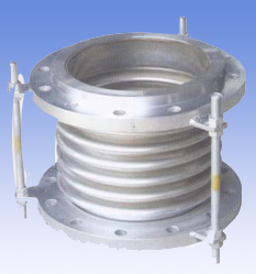
Metal bellows.png
Stiffness calculation of bellows
The stiffness of the bellows is divided into axial stiffness, bending stiffness, torsional stiffness, etc. according to the nature of the load and displacement. At present, in the application of bellows, most of the stress is axial load, and the displacement mode is linear displacement. The following are several main bellows axial stiffness design calculation methods:
1. Energy method to calculate bellows stiffness
2. Empirical formula for calculating bellows stiffness
3. Numerical calculation of bellows stiffness
4. EJMA standard stiffness calculation method
5. TOYO calculation method of stiffness
6. American KELLOGG (new method) calculation method of stiffness
In addition to the above six stiffness calculation methods, there are many other methods for calculating stiffness abroad, which will not be introduced here. Mechanics workers in our country have done a lot of work in theoretical research and experimental analysis of bellows, and have achieved fruitful research results. The main research methods are:
(1) Perturbation method
(2) The initial parameter method of numerical integration
(3) Integral equation method
(4) Perturbation finite element method
All of the above methods can perform relatively accurate calculations on the bellows. However, due to the application of deep theory and computational mathematics, it is difficult to apply in engineering, and it is difficult to master. It needs to be further popularized.
Stiffness Calculation of Metal Bellows Combined with Coil Spring
In the process of use, when the rigidity is required to be large, and the rigidity of the metal bellows itself is small, it can be considered to configure a cylindrical coil spring in the inner cavity or outside of the bellows. This can not only improve the stiffness of the entire elastic system, but also greatly reduce the error caused by hysteresis. The elastic properties of this elastic system mainly depend on the characteristics of the spring and the stability of the effective area of the bellows.
Bending stiffness of bellows
Stress calculation of bellows
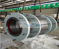
As an elastic sealing part, the metal bellows must first meet the strength conditions, that is, its maximum stress does not exceed the allowable stress under the given conditions. The allowable stress can be obtained by dividing the ultimate stress by the safety factor. According to the working conditions of the bellows and the requirements for its use, the ultimate stress can be the yield strength, the critical stress when the bellows is unstable, or the fatigue strength. To calculate the maximum working stress of the bellows, the stress distribution in the wall of the bellows must be analyzed.
The stress on the bellows is created by the pressure in the system and the deformation of the bellows. The pressure creates hoop (circumferential) stresses on the bellows, and radial film and bending stresses at the sidewalls, troughs, and crests of the waves. A thin shell that cannot resist bending is sometimes called a membrane, and the stress calculated by ignoring bending is called membrane stress. Radial membrane stress and bending stress are generated when the bellows is deformed. When the bellows is working, some are subject to internal pressure and some are subject to external pressure. For example, the bellows of the bellows expansion joints and metal hoses are subject to internal pressure in most cases, while the bellows used for valve stem sealing is generally used. Under external pressure, the stress of bellows under internal pressure is mainly analyzed. The ability of bellows to withstand external pressure is generally higher than that of internal pressure. With the wide application of bellows, people have carried out a lot of analysis, research and experimental verification work on the stress of bellows, and put forward many calculation formulas, calculation programs and charts for engineering design. However, some methods are inconvenient to use due to complicated diagrams or procedures, and some methods assume conditions that are either too simplified or too ideal, and it is difficult to ensure safe and reliable use, and many methods have not been accepted by the engineering community. Therefore, there are very few methods that really meet the practical requirements. Currently, there are two commonly used methods:
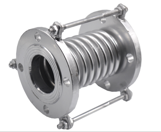
Metal bellows manufacturers.png
1. Numerical calculation of bellows stress
Assuming that all the corrugations of the corrugated pipe are under the same condition, only a single half-wave of the corrugated pipe corrugation is studied in the calculation. In this way, the end corrugations are not considered in the study, although the boundary conditions for the end corrugations are different from those for the intermediate corrugations. The numerical method is based on E. The nonlinear equations listed by Lesnell for the axially symmetric deformation of a rotating thin shell with variable wall thickness are solved. In deriving E. The general assumptions of thin shell theory are applied in the Lessnel equation, including: the assumption that the thickness is small compared to the principal radius of curvature of the annular shell; the assumption of material homogeneity and isotropy. Using the above assumptions will also bring certain errors to the calculation. Because in the manufacture of corrugated tubes, the rolling, deep drawing and subsequent corrugated plastic forming of the tube blank can cause anisotropy and inhomogeneity in the mechanical properties of the material.
2. American EJMA stress calculation method
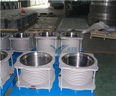
Calculation of effective area of bellows
Effective area is one of the basic performance parameters of bellows. It represents the ability of bellows to convert pressure into concentrated force. In the case where bellows is used to convert pressure into concentrated force output, the effective area is an important parameter.
When the bellows is used in a force-balanced instrument, the stability of its effective area will directly affect the accuracy of the instrument. Therefore, in this case, not only the bellows is required to have a reasonable effective area, but also the effective area is required not to change with the working conditions during the working process.
1. The concept of effective area and the change of effective area
The effective area is an equivalent area over which pressure acts to produce an equal axial force. In general, with the increase of the internal pressure, the effective area of the bellows becomes smaller, and the effective area of the surface becomes larger with the increase of the external pressure.
2. The volumetric effective area of the bellows
Under the action of external force or pressure difference, the ratio of the volume change of the bellows to the change of the corresponding effective length is called the volume effective area.
3. Calculation of effective area of bellows
The requirements for the effective area of the bellows and their calculation method depend on the purpose of the bellows. If the bellows is used as an elastic seal or pipeline thermal compensation, the significance of the effective area is only to calculate the axial force when the bellows is formed and the thrust in the use system. There are some differences between the calculated value of the effective area of the bellows and the measured value. In general, it is sufficient to calculate the effective area of the bellows with a special formula.
When the bellows is used in a force balance instrument and a field platform that needs to convert pressure into force, its effective area should be accurately determined, and it is required to measure one by one.
Other calculations for bellows
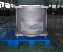
1. Pressure resistance of bellows
Pressure resistance is an important parameter of bellows performance. The maximum static pressure that the bellows can withstand without plastic deformation on the waveform at room temperature is the maximum pressure resistance of the bellows. Under normal circumstances, the bellows works under a certain pressure (internal pressure or external pressure). , so it must withstand this pressure without plastic deformation during the entire working process.
The pressure resistance of the bellows actually belongs to the strength category of the bellows. The key to the calculation is stress analysis, that is, to analyze the stress on the wall of the bellows. As long as the stress at the maximum stress point on the wall of the bellows does not exceed the yield strength of the material, the pressure on the bellows will not reach its withstand pressure.
When other working conditions are the same, the same bellows has better stability under external pressure than under internal pressure, so the maximum pressure resistance under external pressure is higher than that under internal pressure.
When the two ends of the bellows are fixed, if a sufficient pressure is introduced into the inner cavity of the bellows, the crest of the bellows may be damaged by blasting. The pressure value inside the bellows when the bellows begins to burst is called the burst pressure. Burst pressure is a parameter that characterizes the maximum compressive strength of bellows. During the whole working process of the bellows, its working pressure is much lower than the burst pressure, otherwise the bellows will be ruptured and damaged.
When the corrugated length is less than or equal to the outer diameter, the calculated result is very close to the actual burst pressure; for the slender corrugated pipe, the actual burst pressure is much lower. The burst pressure is about 3 to 10 times the allowable working pressure.
2. Stability of bellows
When both ends of the bellows are restricted, if the pressure in the bellows increases to a certain critical value, the bellows will become unstable.
3. Allowable displacement of bellows
For a bellows working in a compressed state, its maximum compression displacement is: under the action of pressure, the bellows can be compressed to the maximum displacement value that can be generated when the corrugations contact each other, also known as the maximum allowable displacement of the structure, which is equal to The difference between the free length of the bellows and the maximum compressed length.
The maximum displacement that can be obtained without plastic deformation of the bellows is called the allowable displacement of the bellows.
The bellows will produce residual deformation in the actual working process. Residual deformation is also called permanent deformation or plastic deformation. The bellows is deformed under the action of force or pressure. When the force or pressure is removed, the bellows does not return to its original state. Residual deformation, the residual deformation is usually expressed by the amount that the bellows does not return to the original position, also known as the zero offset.
The relationship between the displacement of the bellows and the zero offset, no matter the tensile or compressive displacement, in the initial stage of the bellows displacement, its residual deformation is very small, generally less than the allowable zero position specified in the bellows standard offset value. However, when the tensile (or compressive) displacement gradually increases beyond a certain displacement value, it will cause a sudden increase in the zero offset value, which means that the bellows produces relatively large residual deformation. If the displacement is increased a little more, the residual deformation will increase significantly. Therefore, the bellows should generally not exceed this displacement, otherwise its accuracy, stability, reliability and service life will be seriously reduced.
The allowable compressive displacement of the bellows when working in compression is larger than the allowable tensile displacement when working in tension, so when designing the bellows, the bellows should work in compression as much as possible. It is found through experiments that, in general, the allowable compressive displacement of the bellows of the same material and the same specification is 1.5 times the allowable tensile displacement.
The allowable displacement is related to the geometric parameters and material properties of the bellows. In general, the allowable displacement of the bellows is proportional to the yield strength of the material and the square of the outer diameter, and inversely proportional to the elastic modulus of the material and the wall thickness of the bellows. At the same time, the relative wave depth and wave thickness also have a certain influence on it.
4. Bellows life
The life of the bellows is the shortest working period or number of cycles that can guarantee normal operation when used under working conditions. The elastic sealing system composed of bellows often works under the conditions of variable load and large displacement with more cycles, so it is of great significance to determine the service life of the bellows. Because the function of the bellows is different, the requirements for its service life are also different.
(1) When the bellows is used to compensate for the positional deviation caused by installation in the pipeline system, only a few times are required for its life.
(2) The bellows is used in thermostatic controllers with high switching probability, and its lifespan must reach 10,000 times to meet the use requirements.
(3) When the bellows is used as a vacuum seal for a vacuum switch, its lifespan must reach 30,000 times to ensure normal operation.
It can be seen from the above three use cases that due to different use conditions, the required service life of the bellows varies greatly. The life of the bellows is related to the fatigue characteristics of the selected material, and also depends on the size of the residual stress of the formed bellows, the stress concentration and the surface quality of the bellows. In addition, the service life is related to the working conditions of the bellows. For example: displacement, pressure, temperature, working medium, vibration conditions, frequency range, impact conditions, etc.
During the working process of the bellows, its life span mainly depends on the maximum stress generated during the working process. In order to reduce the stress, it is generally achieved by reducing the working displacement of the bellows and reducing the working pressure. In the general design, it is stipulated that the working displacement of the bellows should be less than half of its allowable displacement, and its working pressure should be less than half of the pressure resistance of the bellows.
The test of the currently produced corrugated pipe proves that if the corrugated pipe works according to the above specifications, its service life can basically reach about 50,000 times.
According to the nature of the working pressure, the allowable displacement of the bellows is also different. Generally, when the bellows only bears axial load (tension or pressure), its allowable displacement can be selected between 10% and 40% of the effective length of the bellows; When the bellows is subjected to lateral concentrated force, torsional moment or comprehensive force, the allowable displacement of the bellows should be appropriately reduced.
The application of multi-layer bellows can reduce the stress caused by stiffness and deformation, and thus can greatly improve the life of the bellows.
The service life of GIS bellows will be different when the other conditions are the same but the working pressure properties (constant or alternating load) are different. Obviously, the life of the bellows is shorter when working under alternating load than when working under constant load.

 在线咨询
在线咨询


 简体中文
简体中文